
 Online Service
 - +86-755-32801225
- Info@FibGrid.com
- 008618126154018
- HQLJJHZX
- Ryan Hwang
- +86-755-32801225

 Online Service
 According to ITU-T recommendations, communication optical fibers are classified into seven types: G.651, G.652… G.657. Let's explore the differences among these fiber types.
G.651 Optical Fiber
G.651 is a multimode fiber, whereas G.652 through G.657 are all single-mode fibers.
An optical fiber consists of a core, cladding, and coating, as shown in Figure 1. The cladding diameter is usually 125 micrometers, and the coating diameter (after coloring) is generally 250 micrometers. However, the core diameter is not fixed, and variations in core diameter lead to significant changes in fiber transmission performance.

Figure 1: Structure of an Optical Fiber
The core diameter of a multimode fiber typically ranges from 50 to 100 micrometers. As the core diameter decreases, the transmission performance of the fiber improves significantly. Originally, light signals within the fiber are transmitted in multiple modes, as shown in Figure 2. When the core diameter is reduced, the number of transmission modes decreases, and the interference between them is minimized.

Figure 2: Transmission of Light Signals in a Graded-Index Multimode Fiber
When the core diameter is reduced below a certain threshold, only one transmission mode remains for the light signal, as illustrated in Figure 3, resulting in single-mode fiber.

Figure 3: Transmission of Light Signals in a Single-Mode Fiber
G.652 Optical Fiber
G.652 fiber is the most widely used optical fiber. Aside from drop cables in Fiber to the Home (FTTH) deployments, almost all long-haul and metropolitan area networks utilize G.652 fibers.
In terms of energy distribution, the light signal in a single-mode fiber isn't confined solely to the core; there is also light in the cladding. To describe the concentration of light energy in single-mode fibers, the distance between the two furthest points where the light intensity drops to 1/(e^2) of the maximum intensity at the core is defined as the mode field diameter, as shown in Figure 4.
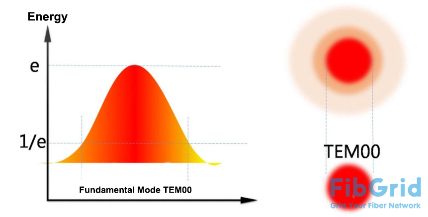
Figure 4: Definition of Mode Field Diameter
Clearly, the mode field diameter better represents the transmission characteristics of single-mode fiber, so the core diameter is no longer emphasized. Mode field diameter is a critical parameter for single-mode fiber, increasing with wavelength.
One of the most crucial factors affecting fiber transmission distance is attenuation. The attenuation coefficient of fiber varies with wavelength. The attenuation coefficients of conventional single-mode fiber are shown in Figure 5. The figure indicates that fiber attenuation is lowest at 1310 nm and 1550 nm, which are the two most commonly used wavelength windows for single-mode fiber.
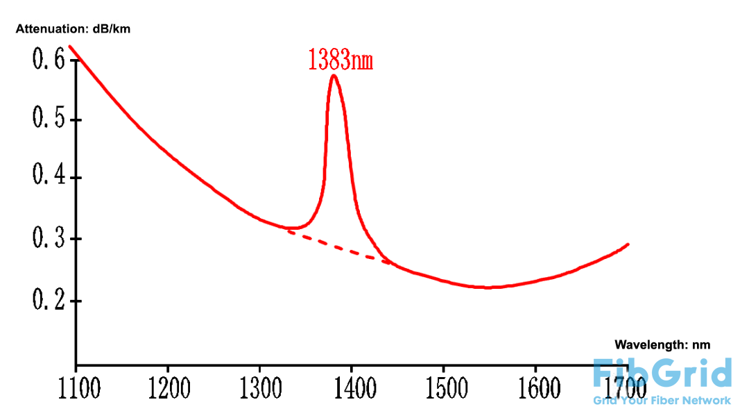
Figure 5: Attenuation Coefficient of Conventional Single-Mode Fiber
G.653 Optical Fiber
As optical communication systems increased in speed, the transmission of signals began to be affected by fiber dispersion. Dispersion refers to the phenomenon where different frequency components or mode components of a signal (pulse) propagate at different speeds, leading to signal distortion (pulse broadening) after a certain distance, as shown in Figure 6.
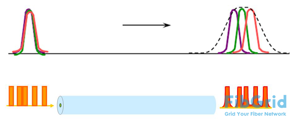
Figure 6: Fiber Dispersion
The dispersion coefficient of a fiber is also wavelength-dependent, as shown in Figure 7. While the attenuation coefficient of single-mode fiber is lowest at 1550 nm, the dispersion coefficient is relatively high at this wavelength. To address this, a single-mode fiber with zero dispersion at 1550 nm was developed, known as G.653.
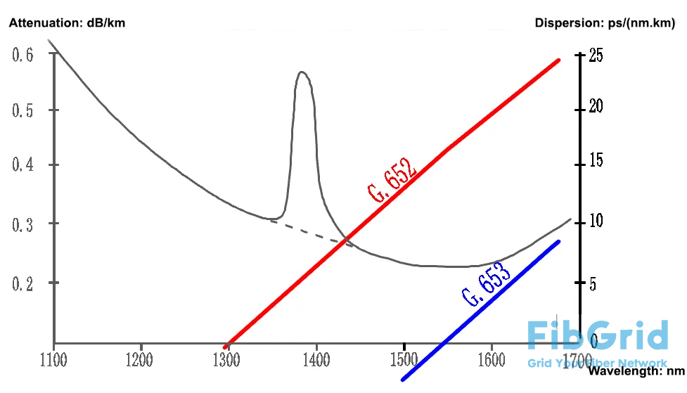
Figure 7: Dispersion Coefficient of G.652 and G.653 Fibers
However, the zero-dispersion characteristic of G.653 fiber is not suitable for Wavelength Division Multiplexing (WDM) systems, leading to its rapid obsolescence.
G.654 Optical Fiber
G.654 fiber is primarily used in submarine cable communication systems. To meet the demands of long-distance, high-capacity submarine communication, G.654 fiber has undergone two major improvements:
Reduced fiber loss: The attenuation has been lowered from 0.22 dB/km (G.652) to 0.19 dB/km (standard value).
Increased mode field diameter: A larger mode field diameter decreases the energy density across the fiber's cross-section, improving the fiber's nonlinear effects and enhancing the signal-to-noise ratio of the communication system.
FibGrid speculates that increasing the mode field diameter may involve enlarging the core diameter. As the core diameter increases, the cutoff wavelength of the fiber also increases. This explains why G.654 fiber is known as the "cutoff wavelength shifted fiber" (with a cutoff wavelength of about 1530 nm, compared to 1260 nm for other single-mode fibers). However, the core diameter cannot be increased too much, as it would turn the fiber into a multimode fiber, making the 1550 nm wavelength unusable.
G.655 Optical Fiber
Due to the zero dispersion at 1550 nm in G.653 fiber, which is unsuitable for WDM systems, G.655 fiber was developed. G.655 fiber has a small but non-zero dispersion at 1550 nm, making it suitable for WDM systems. For over 20 years around the turn of the century, G.655 fiber was the first choice for long-haul trunk lines. The attenuation and dispersion coefficients of G.655 fiber are shown in Figure 8.
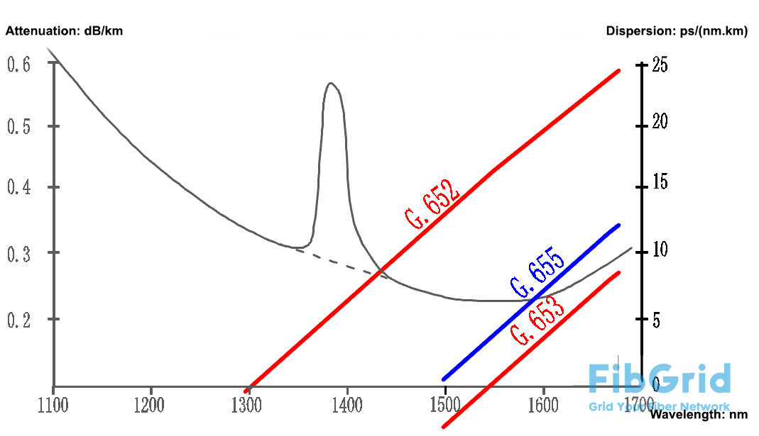
Figure 8: Attenuation and Dispersion Coefficients of G.655 Fiber
However, even the best fiber faces obsolescence. With the maturation of dispersion compensation technology, G.655 fiber was replaced by G.652 fiber. Since around 2005, G.652 fiber has been widely used in long-haul trunk lines, and G.655 fiber is now mainly used for maintaining existing long-haul routes.
FibGrid believes there is another important reason for the obsolescence of G.655 fiber:
The standard mode field diameter of G.655 fiber is 8-11 micrometers (1550 nm). There can be significant differences in mode field diameter among fibers produced by different manufacturers, but the fiber model remains the same. When splicing fibers with significant differences in mode field diameter, the resulting attenuation can be substantial, making maintenance highly inconvenient. As a result, even though G.652 fiber requires more dispersion compensation, users prefer it over G.655 fiber.
G.656 Optical Fiber
Before introducing G.656 fiber, let's revisit the era when G.655 dominated long-haul trunk lines. From an attenuation perspective, G.655 fiber can be used for communication in the wavelength range of 1460 nm to 1625 nm (S+C+L bands). However, due to the low dispersion coefficient below 1530 nm, G.655 fiber is not suitable for WDM systems, restricting its usable wavelength range to 1530 nm to 1525 nm (C+L bands).
To enable communication in the wavelength range of 1460 nm to 1530 nm (S band), G.655 fiber's dispersion slope was reduced, resulting in G.656 fiber. The attenuation and dispersion coefficients of G.656 fiber are shown in Figure 9.
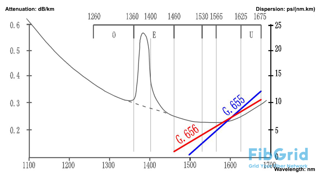
Figure 9: Attenuation and Dispersion Coefficients of G.656 Fiber
FibGrid believes that due to the nonlinear effects of optical fiber, the number of channels in long-haul WDM systems will not increase significantly. Additionally, the cost of building metropolitan optical networks is relatively low, so increasing the number of channels in WDM systems is not very meaningful. Therefore, current Dense Wavelength Division Multiplexing (DWDM) systems still primarily use 80/160 channels, and the C+L bands of the fiber are sufficient to meet the demand. Unless high-rate systems require stricter channel spacing, G.656 fiber is unlikely to see large-scale adoption.
G.657 Optical Fiber
G.657 fiber is the most widely used fiber after G.652. The ultra-thin drop cables used in FTTH deployments contain G.657 fiber.
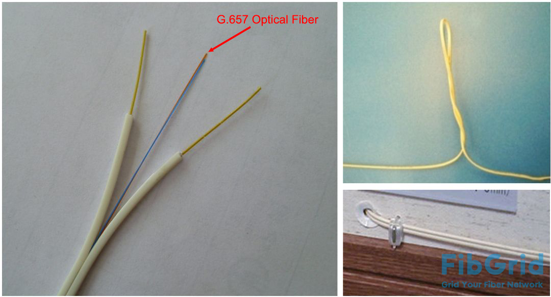
G.657 is a bend-insensitive fiber, with a bending radius less than half that of G.652 fiber.
